

Milling Machine:
A milling machine is one of the most influential and versatile kinds of machines found in the manufacturing industry.
Milling is the most widely used machine used in machine shops and modern manufacturing industries all over the world.
It is a type of machining process in which a cutter having multiple cutting edges is used to remove the material from the workpiece.
This machine tool makes up about 85 percent of the all material removal process.
History of Milling Machine:
The milling machine is believed to come into existence in 17 the century. It was used by the clockmakers at that time.
Then in the 18th century in the united states, a machine was used which was similar to the lathe machine but in this machine,
The cutting tool used to rotate and the workpiece uses to remain stationary.
This was the better-developed form of the Milling machine.
Inventor name: Eli Whitney invented the Milling machine in the year 1818.
During that time, it was used for the making of the gun parts. Eli Whitney got a big order from the government for the production of Musket.
Later he developed a semi-automatic Milling machine which further enhanced the production.
He also added a cutter to the machine.
Now, these machines can perform multiple operations.
Gradually with time now we have the most advanced form of the Milling machine which is the CNC Milling Machine. It is very accurate and has a high production speed.
Definition:
The milling machine is a type of machine which removes the material from the workpiece by feeding the work past a rotating multipoint cutter.
The metal removal rate is higher very high as the cutter has a high speed and many cutting edges.
MRR (Material Removal Rate) can be further increased by increasing the number of teeth on the cutter.
It is the most important machine in the tool room as nearly all the operations can be performed on it with high accuracy.
Milling Machine Application:
It has a wide range of applications. Some of them are:
- Machining flat surfaces
- Slotting
- Machining of contoured surfaces,
- Complex and irregular areas,
- Revolution surface,
- Machining external and internal threads
- Gear cutting
- Machining helical surface of various cross-sections and many more.
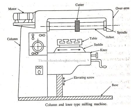
Milling Machine Parts:
The principal parts and their function of the Milling Machine are as follows:
- Base
- Column
- Knee
- Saddle
- Table
- Over-Arm
- Spindle or Arbor
- Arbor supports
- Ram
- Milling Head

Let’s study Milling parts one by one in detail. So,
Base:
It is the part upon which the whole machine parts are being mounted.
It is a type of foundation for the machine.
The base is mostly made up of cast iron, so it has good strength and rigidity.
It also helps in the absorption of shocks.
Cutting fluid can also be stored in the base.
Column:
The main supporting frame which consists of all the driving mechanism and the motor is called the column.
The driving mechanism usually consists of a cone pulley mechanism in which the v-belt is being used to connect it to the motor.
Further by using this driving mechanism the speed of the machine can control as per our requirement.
Knee:
Knee shape is quite similar to that of the human body knee.
The knee is an important part of this machine which supports the other parts like saddle and table.
The knee is attached to the column and has guideways by which it can move up and down with the help of the elevating screw for adjusting its height.
Saddle:
The saddle is present on the top of the knee which further carries the table.
Its basic function is to support the table.
A saddle can slide on the guideways which are exactly at 90 degrees to the column face.
Saddle moves crosswise(in or out) on guideways provided on the knee.
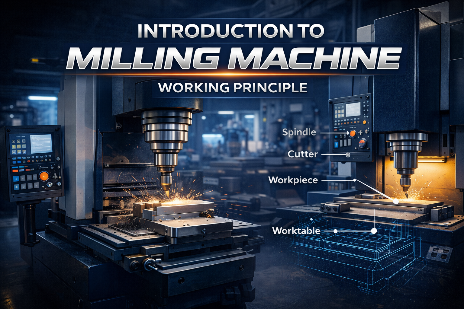
Table:
The table is present on the top of the saddle.
The table consists of T-slots or sometimes fixtures are used for holding up the workpiece on the table.
A table can travel longitudinally in a horizontal plane.
Over-arm:
It is also called as the over-hanging arm.
It is present at the top of the column.
The basic function of the over-arm is to support the arbor and spindle.
Spindle or Arbor:
The top portion of the column contains the spindle.
The spindle is also an important part of the machine as it the part where the multipoint cutter is attached.
Power required for the rotation of the spindle is obtained from the motor through belt, gear and clutch assembly.
Milling Machine Working Principle:
The working principle of the Milling machine is,
- The working principle employed in the metal removing operation on a milling machine is that the work is rigidly clamped on the table of the machine and the revolving cutter which has multiple teeth is mounted on the arbor.
- The cutter revolves at high speed and the work is fed slowly past the cutter.
- The work can be fed in a vertical, longitudinal or cross direction depending upon the type of the milling machine being used.
- As the work proceeds, the cutter-teeth removes the metal from the surface of the job(workpiece) to produce the desired shape.
Milling Machine Types:
The various types of milling machine are:
- Column and Knee Milling
- Vertical Milling
- Horizontal Milling
- Simplex Milling
- Duplex Milling
- Triplex Milling
- Rotary table Milling
- Drum Milling
- Profile milling
- Planetary milling
- Tracer controlled milling
- Pantograph milling
- Universal Milling
- Bed type Milling
- Planer type Milling and
- CNC Milling Machine
These 15 types of Milling machines above shown will be discussed in very detail below.
Let’s start,
Column and Knee Milling machine:
Column and knee mill machine is a versatile machine and is capable of performing a large variety of operations.
This machine is the simplest type of machine.
It consists of a base on which the whole machine parts are being mounted.
It consists of a column that acts as a supporting frame for the machine.
The knee projects from the column which supports the saddle which in turn supports the table mounted on it.
The cutter is mounted on the arbor which does the work of machining the job (workpiece).
Three motions which can be given to the workpiece are:
Vertical motion:
The workpiece can be given vertical motion that is up and down motion with the help of the knee.
The knee is attached to the column by means of guideways through which the vertical motion of the workpiece is possible.
Cross-Motion:
Cross motion is possible as the table which holds the workpiece can have traverse movement.
Longitudinal Motion:
The workpiece can move back and forth by the movement of the saddle present just below the table.
Column and knee type mill machine is a two and half axis machine which means contour can be cut both in the horizontal plane and vertical plane simultaneously and a vertical upward feed is also given that is ½ axis interpolation.
Vertical Milling Machine:
A vertical Milling machine is similar to the knee and column type milling machine the only difference is the position of the cutter-spindle. In a vertical mill machine, the spindle is in a vertical direction which is exactly perpendicular to the table.
In the vertical mill machines, the table is free to move in all the major directions which are horizontal, vertical and transverse directions.
The spindle can move up and down to perform the operations like grooving, drilling, boring, die- forming, slotting, and many other operations.
This type of machine is best suited for performing operations like face milling and end milling operations.
Universal Milling Machine:
Universal Milling Machine is a type of milling machine in which the swivel is used.
Swivel is placed on the saddle and the workpiece is placed on the swivel which permits the machining operation at the desired angle.
A universal mill machine is used for making cuts on helical gears and flute drillings.
So a universal mill machine finds an indispensable position in the tool-rooms and is known for producing very accurate work.
Bed-type Milling Machine:
A bed-type mill machine is a type of machine in which the workpiece is directly mounted on the main body of the machine, making it strong and robust.
In this, the knee is not present and the table can move longitudinally over the bed ways. More than one spindle can be used so that different operations can be performed simultaneously.
On the basis of the number of spindle head used in the mill machine it can be divided as follows:
Simplex bed Machine: It has single spindle heads.
Double bed Machine: It has double spindle heads.
Triple bed Machine: It has triple spindle heads.
The cutter is usually made of Carbide. The other available versions of the machine are Horizontal, vertical, planer or boring milling machine.
Advantage:
i) This type of milling machine is known for its rigid structure, which helps in the high production of the interchangeable jobs.
ii) It can withstand heavy cutting loads for a long time in the production work.
iii) Use of the multiple spindles which help in performing different operations simultaneously. Thus, increasing the overall production process in the manufacturing industry.
iv) It is mostly automatic so lesser attention of the operator is required.
Disadvantages:
Less Flexibility: Bed type mill machine is less flexible than Knee and column type mill machine since it is suited for the jobs where the changes in the setup are not much frequent.
High power: Huge power is required for the cutting.
Planer-Type Milling Machine:
The Planer type mill machine has features similar to the Planer. The movement of the table is slightly slower than the actual planner.
In this machine, the tool head is being replaced by a milling head, which is mounted on the cross-rails of the planer.
Rotating cutters of the milling heads do the milling operation on the job.
Both the above things, that is the table movement and the rotating cutters make the machine different from the Planer.
The cutter–spindle has two movements:
- Transverse movement.
- Vertical movement
Use: Planer type milling machine is used for doing milling operations on very big jobs.
Milling Machine Operations:
The milling machine does not give a continuous cut like in the case of the Lathe Machine.
First, the wheel of the cutter slides on the surface followed by the crushing movement and then the cutting movement by which the unwanted material is removed from the workpiece.
A large number of the operations can be performed on the milling machine some of them are as follows:
- Plain Milling or Slab Milling Operation
- UP and DOWN Milling Operation
- Face Milling Operation
- End Milling Operation
- Gang Milling Operation
- Straddle Milling Operation
- Groove Milling Operation
- Gear Milling Operation
- Side Milling Operation and
- T-Slot Milling Operation
Plain Milling or Slab Milling Operation:
Plain or the slab milling is a process in which the plain, horizontal or flat surfaces are produced, which are parallel to the axis of the rotation of the cutter.
Peripheral mill cuter is used for performing the slab milling operation.
Up Milling and Down Milling:
Up milling is a method of milling operation in which the cutter and the workpiece both moves in the opposite direction.
Down Milling is a method of milling operation in which the direction of the rotation of the cutter coincides with the direction of the work feed.
Chip Thicknesswill be minimum in the beginning and maximum at the end in the case of up -milling. Whereas, the chip thickness will be greater in the beginning and lesser at the end in the case of down-milling.
Tool Life will is more in the case of down-milling as compared with the up-milling.
The surface finish will be more in the case of the down-milling as compared with the up-milling method due to which down-milling method is used for the finishing operations in the industries.
Accuracy will be more in the case of up-milling as compared with the down-milling process since in up-milling the workpiece is pulled against the table so the fasteners will be under tension and we know that under tension the backlash error will not have any effect which ultimately results in the better accuracy in up-milling.
Face Milling Operation:
It is a type of milling operation in which the layer of material is removed from the face of the material.
The end milling cutter is preferred for performing face milling operations.
In Face Milling operation the teeth for cutting are present on both the periphery and the face of the cutter.
The axis of rotation of the cutter is perpendicular to the work surface. In face milling most of the cutting is done by the periphery portions of the teeth, the face portion provides finishing the action.
End Milling Operation:
End milling is the combination of the slab milling and face-milling operation and used for creating slots in the workpiece and mostly used for handling the complicated profile.
Gang Milling Operation:
Gang milling is a type of milling operation in which multiple cutters are being mounted on the same arbor to produce the desired shape on the workpiece.
Straddle Milling Operation:
The straddle is the type of milling process in which milling is performed on two surfaces simultaneously.
T-slot milling is a unique example of straddle Milling.
Milling Machine Indexing:
Definition:
The operation of rotating the job through a required angle between two successive cuts is called Indexing.
Sometimes when the high precision work is being done on a mill machine then the accuracy of the spacing of the teeth is very important.
For example – Indexing is most required while manufacturing gears teeth, cutter teeth, etc.
Indexing is possible with the help of a milling attachment which is known as dividing head. It is a kind of an accessory to the machine.
It helps to divide the periphery into equal divisions that are square, octagonal, hexagonal.
Now let’s discuss the dividing head in bit detail:
Dividing Head:
Now let’s discuss the dividing head in bit detail:
The two important parts of the dividing head are:
Index-crank:
It is a device that is used to rotate the job.
The index- crank can be rotated about its axis. The rotation of the crank is transmitted through a gear to the job so that the number of complete revolutions will result in a certain revolution of the job.
The ratio of the crank and the shaft on which job is mounted is 40:1 that is when the index plate makes 40 revolutions, the job makes one revolution.
Index- Plate:
Index- Plate basically ensures that the job has been rotated through the desired angle.
The index plate has a number of holes arranged concentrically so that each circle has a number of holes equally spaced.
Common Methods of Indexing:
The common methods of indexing are as follows:
- Direct Indexing.
- Simple or plain indexing.
- compound indexing
- Differential indexing.
- Angular indexing.
Milling Cutters:
The cutters are the most important part of the machine which is used for removal of the material from the surface of the workpiece.
The availability of a large variety of the milling cutter makes it the most versatile machine used in the industries.
Milling cutters material:
The various material used for making up of the milling cutters are:
- High Carbon Steel.
- High-speed steel.
- Sintered carbide tip.
- Stellite.
Out of all the above four mentioned material for the used for the making of the cutter, High Carbon Steel is less used because the cutters made from it get dull quickly if high cutting speed and feed are used.
Various grades of Highspeed steel are used extensively for the making of the cutter because they maintain a keen cutting edge even at high temperatures and thus can be easily used at high speed.
Brief Geometry of the Milling Cutter:
The four important angles involved in the making of the milling cutter are:
1. Radial Rake angle:
The radial Rake angle of the milling cutter is equal to the side rake of the single point tool.
2. Axial Rake:
The axial Rake angle of the milling cutter is equal to the Back Rack of the single point tool.
3. Radial Relief.
4. Axial Relief.
If the radius of the cutter lies along the face of the milling cutter then it is said to have a zero Rake.
Another factor which should be taken care while production of the cutter is:
Clearance Angle:
The angle between a line through the surface of the land and a tangent to the periphery at the cutting edge.
A clearance angle is given to prevent the back of the tooth from rubbing against the workpiece.
Generally, cutters having a diameter above 75mm will be given a clearance of 3 to 5 degrees.
In the case of the small diameter cutters, a large clearance angle is given to eliminate the tendencies for teeth to rub against the job(workpiece).
Clearance angle also depends upon the work material like for,
- Cast Iron (C.I): The clearance angle for the cast iron is 4 to 7 degrees.
- For soft Metal like Mg, Al, Brass the clearance angle is 10 degrees to 12 degrees.
Milling Machine Cutters:
The various type of Milling cutters used in the different type of the milling machine are as follows:
- End Milling cutter
- Peripheral Milling cutter
- Side Milling cutter
- Straddle Milling cutter
- Gang Milling cutter
- Staggered Milling cutter
- Concave Milling cutter and
- Cylindrical Milling cutter
Now let’s discuss each type of Milling cutter in brief:
1. End Milling cutter:
End mill cutters are the type of cutters used in the milling machine which has teeth at the end or at the face of the circular disk.
This type of cutter is mostly used with the vertical mill machine.
An end mill cutter should be selected which has the geometry and cutting-edge angle compatible with the job (workpiece) being machined so as to minimize side thrust, avoid tooth and shank breakage, minimize wear and maximize the material removal rate.
2. Periphery Milling cutter:
When the cutting teeth are present on the periphery of the circular disk then it is known as periphery mill cutter.
Periphery Mill cutter can only be used for the Horizontal mill machine.
3. Side Milling Cutter:
Side Mill cutter is a type of cutter in which the cutting teeth are present on the periphery and also at the face or end.
This milling cutter is mostly used in straddle Milling operations and face Milling operation.
It is also used for cutting slots and milling deep and narrow slots.
4. Face Milling Cutter:
Face mill Cutter consists of a large diameter cutter body with a number of mechanically fastened inserted tools.
By making radially deep and axially narrow cuts a large volume of the material is removed.
The diameter of the cutter body depends upon the length of the workpiece and the clearance available on either side of the workpiece.
Face Mill cutters are used in the down Milling.
Face Milling cutter is very rigid and the surface finish depends upon the feed rate and the number of teeth.
5. Gang Milling cutter:
Gang mill cutter is a type of cutter in which the peripheral milling cutters of the different sizes are cut together to remove the material simultaneously from the workpiece.
6. Staggered Mill Cutter:
Staggered Mill cutter has their teeth staggered at the periphery with alternate right-hand and left-hand helix angles and are made in relatively narrow width.
7. Concave Milling Cutter:
The concave milling cutter is a type of formed cutter. Formed Cutter is designed to produce a specific shape on the workpiece.
Concave Milling Cutter is a type of cutter which is shaped to mill a convex surface of circular contour equal to half a circle or less.
8. Cylindrical Milling Cutter:
Cylindrical Milling Cutter is the type of cutter which has a cylindrical shape and has teeth on the circumferential surface only.
Precautions should be followed when the use of Metal cutter in Milling Machine:
The various precautions which should be followed while using a metal cutter are as follows:
1. It should be stopped before setting up or removing the metal cutter or workpiece or any other accessories.
2. In case if the cutting teeth are dull, then it should be sharpened using a cutter grinder.
3. Bur should be removed from the milling cutter before using it for further milling process.
4. All the chips should be removed from the cutter before using it for new milling work.
5. The cutting speed, feed, and cutting fluid should be most appropriate for the material, cutter, and milling process.
6. The cutter when should be stored properly in the racks. It should be ensured that the teeth do not hit other cutters or metal parts.
7. The workpiece and cutter should be kept as cool as possible and the cutter should be rotated in the right direction only.
Advantages of Milling Machine:
The various advantages are:
High speed:
In Milling, the rate of metal removal is very high as the cutter rotates at a high speed and has multiple cutting edges.
Better surface finish:
The surface finish of the materials machined on the milling machine is better because of the multi-cutting edges.
Increased Productivity:
CNC Milling Machines are the machines in which the milling operation is being controlled by software.
It has increased the overall production with better finish and accuracy.
High Accuracy:
In the milling machine, the products machined are of high accuracy especially in the case of the most advanced form of milling machine which is the CNC Machine.
Huge Application:
Indexing head makes it suitable for so many applications as the exact rotation of the job is possible by the use of it.
Milling can be used for machining flat surfaces, irregular surfaces, contoured surfaces, slotting, gear cutting and many more.
Milling Machine disadvantages with remedies:
The disadvantages of the milling machine are as follows:
- High Flank wear
- High creator wear
- Breaking of carbide
- High chatter
- chip clogging
High Flank wear:
It has a high flank wear rate which can be prevented by reducing speed and increasing the feed rate.
Further to avoid it one should use harder carbide with proper geometry and sharpened cutting edges.
High crater wear:
High crater wear is found which can be tackled by reducing speed and using harder carbide.
Breaking of carbide:
Sometimes the production process gets hindered because of the breaking of the carbide.
The remedy for this problem can be the use of tougher carbide, and rigidity of the cutter, machine, and arbor should be ensured.
High Chatter:
This happens due to poor rigidity of cutter, machine, loose arbor, and improper geometry.
This situation can be improved by increasing feed, reducing speed and using unequal pitch cutters.
Chip clogging:
The milling machine also suffers from the problem of chip clogging which can be reduced by using reducing the number of teeth on the cutter and increasing speed and chip pockets.
